How to Read Blueprints
This tutorial will show you how to read blueprints for all the common house plan views.
Also see our Make Your Own Blueprint tutorial for those wanting to do their own house plan drafting.
There are three basic house construction plan views:
- Elevations
- Floor plans
- Cross-sections
Elevation Drawings
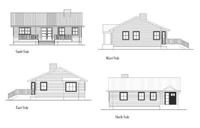
When deciphering a set of house blueprints, you should look first at the elevation views.These views will give you an overall idea of what the exterior of the finished house will look like.
Typically a set of house plans will include four elevation drawings, one for each of the front, rear and two sides of the house. The elevation view is a completely flat view, in other words, with no artistic perspective.
The elevations detail the building height, the exterior materials used, including siding and roofing. They help give the prospective owner an idea of what the home will look like but are also used by the municipal planning office before issuing a building permit to ensure that the building meets the local zoning regulations. The elevation drawings are also used by the building trades when finishing the house exterior.
Floor Plans View
The next blueprint view to understand is the floor plan. This drawing shows the house from what is called "plan" view - looking at the house from above as though the viewer was in the sky looking directly down on the house with the roof removed. This view shows all walls, room sizes, appliances, plumbing fixtures (sinks, toilets) and sometimes furniture.
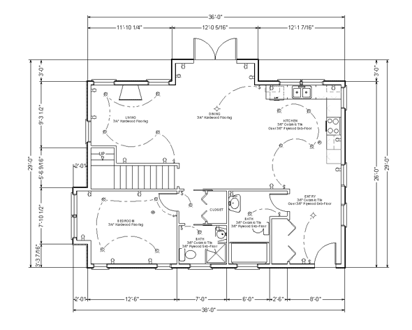
Floor plans also usually indicate finishing information such as flooring types, location of electrical switches, plugs and lights as well as built in fixtures such as cabinetry, sinks, toilets and kitchen appliances.
To understand the various symbols shown on the floor plans, first open our blueprint symbols glossary. This glossary will open in a new window so you can easily switch back and forth between the How to Read Blueprints tutorial and the symbols glossary as needed.
Let's start with the walls.
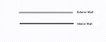
Walls are indicated by a double line. The thicker the wall, the further apart the two lines will be. An interior wall will usually consist of the wood framing covered on both sides with drywall. (Drywall is the common name for the inside walls of your house that are painted or wallpapered). Interior walls can also be made of bricks (adobe or concrete) or other materials. Exterior walls will typically be wider than the interior walls since the exterior walls are usually structural (they help hold up the floors above and the roof). The exterior wall could be made of wood or metal framing, concrete (perhaps with insulated forms), straw bale, rammed earth, cob, adobe bricks or anything that passes your local building code. The inside walls of the exterior walls are often covered with drywall or stucco and the outside walls covered with either stucco or sheetboard (usually plywood or oriented strand board) which is then covered with some type of breathable waterproofing, then covered with exterior surfacing (wood siding, brick, stucco, etc.) Typically, the exterior walls will appear thicker than the interior walls on your blueprints.
Which brings us to scaling.

Blueprint Scale
All blueprints are drawn to scale. This means that they are an exact representation of the real house as it will be built but they are scaled down to fit onto paper. Think of it as though you have drawn them full size and then used a massive photocopier to reduce their size by a reasonable percentage.
The reduction is not random however. The draftsperson or architect will draw them to a specific scale. An example of a scale could be one inch to one foot (written as 1":1'). So if the house was 40 feet long, the draftsperson would draw the house on paper as 40 inches long.
Now 40 inches would make for cumbersome blueprints so the scale that is more commonly used is 1/4 inch to one foot (written as 1/4":1'). So here we do the math, if we have a 40 foot long house and every foot will be represented by 1/4" we will draw it as 1/4 inches per foot X 40 feet which equals 10 inches. This will fit nicely on a piece of 11" X 17" paper. For framing details, 1/2":1' is often used. The same 40' long house would then appear on paper as 1/2 inch per foot X 40 feet which equals 20 inches. At this scale, the drawings are often on 18" X 24" or even 24" X 36" size paper.
The scale used on a set of house plan drawings will be listed somewhere near the page title block. Look on the page for 1/8":1', 1/4":1' or 1/2":1'.
To make reading blueprints and measuring your house dimensions easier, an architect's scale will come in handy. They are about the size of a standard ruler. Many office or art stores sell these. The scale is triangular shaped with two scales on each side. The side shown below shows a 1/4":1' scale going from right to left (on the other end of this side but not shown is the 1/8":1' scale).
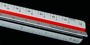
Look on the right-hand side of the scale in the image above. You will see the numbers 0, 2, 4 going from right to left. If you had house plans that had 1/4":1' written near the page title, you would use this part of the architect's scale. If you were to place the 0 on the inside line of an interior wall on your house plans, you could then measure across to the inside line of the opposite room wall. Simply read the number on the scale as though it were feet. So if the opposite wall of the room lay at the number 12 on the scale, the room is then 12' wide. The very fine gradations to the right of the 0 represent inches.
Cross Section Drawings
The final views of house construction drawings are the cross-sections. A cross-section shows a "slice" of the house. Imagine taking a doll house and then cutting it from the top like a loaf of bread. If you took any one of the slices and looked at it from the flat face you would have a cross-section of the doll house. Below is an example of a cross-section through the stairwell of a house.

The cross section could very well be the most difficult view in learning how to read blueprints since a large amount of detail and layers can sometimes be included. In our doll house example, imagine if the "slice" was very thick and included in it a few layers of walls, as well as some doorways, fixtures such as bathtubs and sinks, and details for a built-in cabinet. The residential designer or architect will often use the cross-section view to detail interior finishing such as built-ins, trim work and stairway finishing for the construction crew who will be doing this work. This view is also invaluable to the framers since it will give a better picture of how the house is to be built. Since the cross section can also show a slice of the exterior walls, information about the details of the wall layers, their insulation and exterior cladding can be included in this view. Often full house blueprints will include several cross-sections. A more complicated and detailed house will require more cross-section drawings.
